PRODUCT INFORMATION: Bolt-type force control of heavy metal gecko is expanding anchor. You can add type to install, its advantage Is the hole in advance to be anchored component should be directly placed in the anchor position, drilled through the hole, and drilled a hole in the anchor base, The net can be placed after the anchor bolt hole, put installation torque. Easy to save time, avoid the drill hole of trouble again, no Needs special drilling and installation tool for non-cracked concrete of medium and heavy-duty anchor: Machine set up equipment base, support beams, railings, overhead, brackets, and heavy equipment.
1. Drill holes on the base according to the required diameter and depth
2. Move debris and clean small holes
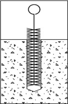
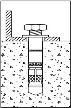
3. Knock this heavy gecko into the hole
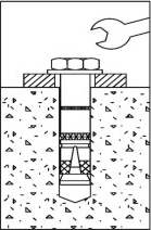
4. Tighten the screws with a wrench
What Makes This Anchor Different
The Pass-Through Installation Principle
The Bolt Heavy Duty Shield Anchor solves a problem that conventional expansion anchors cannot: the need to anchor through a pre-existing hole in the fixture material without removing and repositioning the fixture between drilling and anchoring operations.
With wedge-type anchors, the fixture must be removed after drilling the concrete, the anchor inserted and torqued down, and then the fixture re-positioned and bolted on. With the bolt-type shield anchor, the anchor body passes through the clearance hole already present in the fixture material — both the concrete drilling and the anchor installation are completed in a single positioning of the fixture plate.
This distinction is not merely procedural. In large-scale equipment installation projects — machinery bases, overhead crane rail brackets, structural support beams — re-positioning a heavy fixture between drilling and fastening operations costs time, requires additional labour, and introduces cumulative positioning error that bolt-type shield anchors eliminate entirely.
Installation MethodPass-through the fixture clearance hole
Two fundamentally different expansion control methods exist in heavy-duty mechanical anchors: torque-controlled (the bolt is tightened to a specified torque, which drives expansion) and displacement-controlled (the expansion is set by driving to a defined depth, independent of torque).
The Bolt Heavy Duty Shield Anchor is torque-controlled. Turning the bolt draws the conical plug upward into the shield sleeve, forcing the sleeve segments outward against the concrete hole wall. The expansion force is a direct function of the applied torque — which means a calibrated torque wrench both installs and verifies the anchor in a single operation.
This provides a measurable quality control checkpoint at the installation stage that displacement-controlled anchors do not offer. On supervised construction sites and equipment installation projects where installation records are required for structural sign-off, torque-controlled anchors produce a documentable installation parameter that can be recorded, audited, and re-checked by a third party after installation.
Quality VerificationFinal torque value — measurable and recordable
Re-inspectionTorque check on installed bolt post-installation
Tool RequiredStandard metric torque wrench — no special setter
Mechanical Working Principle
How the Conical Bolt Expansion Mechanism Develops Load Capacity
Understanding the mechanics of shield anchor expansion — how the bolt, cone, and sleeve interact at each installation stage — helps procurement teams assess product quality beyond surface appearance, and helps site engineers troubleshoot performance issues before they become structural problems.
Expansion Sequence — Stage by Stage
1
Resting State — Anchor Inserted
The anchor is driven through the clearance hole of the fixture and into the pre-drilled concrete hole. At this stage the shield sleeve is at full diameter — just narrow enough to pass through the concrete hole — and the conical bolt head sits at the bottom of the sleeve without applying outward force. The anchor is retained only by friction of the sleeve against the hole wall, providing no structural load capacity.
2
Initial Torque — Cone Begins Ascending
As the hex bolt is tightened from above, the threaded bolt body draws the conical head upward relative to the sleeve. The tapered geometry of the cone forces the pre-slotted segments of the shield sleeve to splay outward. During this stage, sleeve segments contact the concrete aggregate at multiple points around the circumference of the hole, distributing the bearing load uniformly. The anchor begins to develop measurable pull-out resistance.
3
Target Torque — Full Expansion Achieved
At the specified installation torque, the cone has been drawn fully into the designed engagement position within the sleeve. The sleeve segments are expanded to maximum diameter, pressing against the concrete at the rated contact area. The friction and mechanical interlock between the expanded sleeve and the rough concrete aggregate surface at this stage represents the anchor's rated pull-out and shear resistance. The washer bears uniformly on the fixture plate, transferring load from the structure into the anchor system.
4
In-Service Load State — Self-Locking Behaviour
Once the anchor is fully expanded and load is applied in service, the cone-to-sleeve geometry provides a partial self-locking function: tensile load on the bolt body tends to draw the cone further into the sleeve, maintaining or increasing the outward force on the sleeve segments. This is a key advantage over clip-only wedge anchors, where service tensile load alone does not independently reinforce the expansion state after installation torque has been applied.
Structural Advantages of the Shield Design
Bearing Area
The shield sleeve provides a substantially larger concrete contact area than the narrow clip of a wedge anchor at equivalent diameter. The oversized gasket (outer diameter 21–50 mm depending on size) distributes surface bearing load from the structure into the anchor body, preventing localised concrete crushing under the washer face on medium-strength substrates.
Vibration Resistance
The multi-segment sleeve remains in full contact with the concrete wall over a longer engagement length than wedge-type clip designs. Under cyclic dynamic loading — compressor bases, generator sets, conveyor structure supports — the shield type maintains more consistent preload retention between inspection cycles than clip-type anchors of equivalent shaft diameter.
Shear Capacity
The full-diameter shield body, bearing against concrete along its entire embedded length, provides effective shear resistance across the concrete surface plane. For connections where both tension and shear are simultaneously present — typical of equipment anchors under operational loads — the shield geometry distributes the combined load more effectively than a narrow-shank wedge design.
Installation Tolerance
The clearance hole in the fixture is sized larger than the anchor body (fixture hole diameter exceeds concrete hole diameter by 2 mm per size). This deliberate difference accommodates the minor positional variation that occurs when marking and drilling through a heavy fixture plate, without requiring precise alignment between fixture hole centres and drilled hole centres — a practical advantage on large equipment bases with multiple anchor points.
No Special Tools
Unlike hammer-set or displacement-controlled anchors that require proprietary setting tools to achieve rated performance, the bolt shield anchor requires only a standard rotary hammer drill and a calibrated metric torque wrench. Both tools are present on every professional construction site, eliminating the dependency on specialist equipment that creates procurement and site logistics complications.
Installation Sequence
Five-Stage Pass-Through Installation Sequence
The installation workflow for a Bolt Heavy Duty Shield Anchor differs from wedge anchor installation in one critical stage: the fixture plate is placed over the drilled holes before the anchor is inserted, rather than after. This sequence is the defining operational advantage of the bolt shield anchor type in equipment installation and structural connection work.
01
Position and Clamp the Fixture
Place the fixture plate, equipment base, bracket, or structural element in its final installation position. Verify level and alignment with precision instruments before proceeding. The fixture does not need to be removed again — all subsequent operations are performed with the fixture in its permanent final position.
Key Step
02
Drill Through Both Fixture and Concrete
Using a carbide rotary hammer bit sized to the concrete hole diameter specified for the anchor (e.g. 12 mm for M8, 15 mm for M10), drill through the clearance hole in the fixture and into the concrete substrate to the minimum depth specified. The fixture clearance hole is pre-fabricated 2 mm larger than the drill bit — it guides the drill without obstructing passage.
03
Clean the Concrete Hole
Blow out the concrete hole with compressed air directed past the fixture clearance hole. Due to the constrained access through the fixture aperture, use a blow tube with a nozzle sized to pass through the clearance hole diameter. Brush cleaning through the fixture hole is possible with a wire brush on a flexible extension. Do not allow drilling debris to remain in the hole.
04
Insert Anchor Through Fixture Hole
With the washer already on the bolt above the shield sleeve, insert the complete anchor assembly through the clearance hole in the fixture and into the concrete hole. Drive the anchor downward by tapping the bolt head with a hammer until the shield base reaches the minimum specified depth. The washer will sit flush on the fixture plate surface.
Pass-Through Stage
05
Torque to Specification
Using a calibrated torque wrench, tighten the bolt to the installation torque value for the anchor diameter. Tightening draws the conical bolt head upward into the shield sleeve, expanding the sleeve segments against the concrete hole wall. When the torque wrench clicks at the set value, the anchor is fully installed. Record the torque value per anchor for project quality documentation.
Verification Point
When multiple anchors are being installed in a single equipment base or bracket, tighten all anchors to 50% of the target torque before completing the final torque round. This ensures uniform load distribution across all anchor points and prevents the base plate from rocking during progressive tightening.
Product Family Comparison
Bolt Type vs. Screw Type Heavy Duty Shield Anchor — Choosing Correctly
The Bolt Heavy Duty Shield Anchor and the Screw Heavy Duty Shield Anchor use the same shield sleeve expansion principle but differ in how the expansion force is generated and how the anchor interfaces with the fixture. Selecting the wrong type for an application creates unnecessary complexity on-site that is difficult to correct after installation has begun.
Bolt Type (This Product)
Expansion MethodHex bolt tightened from above — draws conical head upward into sleeve, expanding segments outward against concrete wall
Fixture InterfaceBolt passes completely through the fixture clearance hole; washer and nut bear on the top face of the fixture
Installation SequenceFixture is in final position before drilling — no repositioning required at any stage of installation
Torque MeasurementDirectly measurable with a standard torque wrench on the exposed bolt head — straightforward post-installation verification
Ideal ApplicationEquipment bases, support beams, brackets, handrails, and overhead structures where fixture position must be established before anchor installation
AdjustabilityBolt can be fully removed and replaced without anchor extraction — allows fixture removal for maintenance while anchor remains in concrete
VS
Screw Type
Expansion MethodMachine screw drives the expansion from below — screw threads directly into the anchor body, pulling the sleeve upward over the cone from beneath
Fixture InterfaceAnchor sets in the concrete first; the machine screw is then threaded into the set anchor through the fixture hole to clamp the fixture
Installation SequenceAnchor is installed and expanded before the fixture is placed — fixture is then positioned over pre-set anchors and screws are tightened
Torque MeasurementAccessible on the screw head — measurable, but expansion occurs within the concrete and is less directly observable than the bolt type
Ideal ApplicationApplications where anchor positions are fixed by layout drawing and the fixture can be accurately positioned over pre-set anchor points — cleaner appearance at the connection interface
AdjustabilityScrew can be removed for fixture replacement; anchor body remains permanently set in concrete — connection can be re-made multiple times
When the fixture layout is known in advance and positional accuracy of anchor placement is high, the screw type offers a cleaner installation. When the fixture itself defines the anchor positions — as is typically the case with pre-fabricated equipment bases — the bolt type eliminates layout error by using the fixture as a drill guide. Contact our team to discuss which type is appropriate for your specific connection detail.
Key Product Parameters
M8–M20Diameter range — 5 standard sizes from M8 to M20
Understanding the Three Critical Hole Diameters in Shield Anchor Installation
A shield anchor installation involves three distinct hole diameters that must be correctly understood and coordinated: the concrete hole diameter (drilled in the substrate), the fixture clearance hole diameter (pre-fabricated in the fixture plate), and the anchor body outer diameter (the physical size of the shield sleeve). Confusing these three values is the most common cause of installation failure in shield anchor systems.
A
Concrete Pore Size — The Drill Bit Diameter
This is the diameter of the hole drilled into the concrete substrate using a carbide rotary hammer bit. The concrete hole must be drilled to match the shield sleeve outer diameter — the anchor body must fit snugly into the concrete hole for the expansion mechanism to work correctly. An oversized concrete hole reduces the contact area of the expanded sleeve segments against the concrete, proportionally reducing pull-out resistance.
The drill bit diameter equals the concrete pore size specified in the product table. For M8 anchors this is 12 mm; for M10 it is 15 mm; for M12 it is 18 mm. These values are non-negotiable — do not substitute the nearest available bit size without confirming it is within the tolerance specified by the manufacturer.
Fixed Object Aperture — The Fixture Clearance Hole
This is the diameter of the pre-existing hole in the fixture plate (equipment base, bracket, beam flange, or structural member) through which the anchor body passes. This hole is always 2 mm larger than the concrete hole diameter, providing just enough clearance for the shield sleeve to pass through while the washer sits on the fixture surface above.
The clearance hole also serves as a drill guide when drilling through the fixture into the concrete — the carbide bit passes through the clearance aperture and enters the concrete below. This is the mechanism that makes drill-and-install in a single fixture-positioning operation possible. The 2 mm clearance also accommodates minor misalignment between the fixture aperture centre and the drilled hole centre.
Washer (Gasket) Outer Diameter — The Surface Bearing Zone
The washer outer diameter is the largest external dimension of the anchor system, and the primary surface through which the fixture clamping load is distributed into the fixture plate. A larger washer outer diameter distributes the bolt clamping force over a greater area, reducing the localised bearing pressure on the fixture surface — critical when anchoring into relatively soft fixture materials such as aluminium plate, timber, or thin steel.
The washer outer diameter in this product range is substantially larger than the clearance hole — for M8 it is 21 mm against a 14 mm clearance aperture; for M20 it is 50 mm against a 30 mm aperture. This proportional increase ensures the clamping zone area scales appropriately with the bolt diameter and expected load magnitude.
Size-by-Size Dimensional Data for All Available Lengths
Each anchor diameter is available in multiple lengths to accommodate varying fixture thicknesses. The maximum installation thickness value defines the usable range — select the shortest anchor length where the maximum installation thickness meets or exceeds your actual fixture plate thickness, to maximise the concrete embedment depth achieved.
M8
Length 90 mmMax. 15 mm fixture
Length 110 mmMax. 40 mm fixture
Concrete hole12 mm
Clearance hole14 mm
Washer OD21 mm
Min. depth80 mm
M10
Length 100 mmMax. 20 mm fixture
Length 120 mmMax. 40 mm fixture
Length 140 mmMax. 60 mm fixture
Concrete hole15 mm
Clearance hole17 mm
Washer OD24 mm
Min. depth90 mm
M12
Length 120 mmMax. 25 mm fixture
Length 150 mmMax. 50 mm fixture
Concrete hole18 mm
Clearance hole20 mm
Washer OD30 mm
Min. depth105 mm
M16
Length 145 mmMax. 25 mm fixture
Length 170 mmMax. 50 mm fixture
Concrete hole24 mm
Clearance hole26 mm
Washer OD40 mm
Min. depth125 mm
M20
Length 175 mmMax. 30 mm fixture
—Single length
Concrete hole28 mm
Clearance hole30 mm
Washer OD50 mm
Min. depth155 mm
Select anchor length based on fixture plate thickness. The minimum concrete embedment depth is fixed per diameter — anchor length must be sufficient to achieve minimum embedment after accounting for the fixture plate thickness. For fixture thicknesses approaching the maximum installation thickness limit, verify that the remaining exposed thread length above the washer is sufficient for nut engagement.
Where This Anchor Is Specified
Six Application Categories Where Bolt Shield Anchors Outperform Alternatives
The bolt shield anchor occupies a specific niche in the heavy-duty fastening hierarchy — applications where the combination of high load capacity, pass-through installation geometry, and torque-verifiable installation quality are simultaneously required. Each category below represents a genuine engineering scenario where the product's characteristics provide specific advantages.
Industrial
Machine Base Anchoring
CNC machines, hydraulic presses, compressors, and precision manufacturing equipment require anchor systems that can be installed without moving the equipment after final positioning. Once a multi-tonne machine is levelled on its mounting pads, re-positioning is not practical — bolt shield anchors are installed through the cast base feet directly into the floor slab in a single drilling operation.
Critical parameter: Vibration resistance over years of cyclic operation. The shield sleeve's extended concrete contact length maintains consistent preload better than wedge-clip anchors under long-term dynamic loads from machinery operation.
Structural
Support Beam and Column Base Plates
Steel column base plates and beam support brackets arrive on-site pre-fabricated with bolt holes at exact spacings. Bolt shield anchors allow these pre-fabricated elements to be set in position and anchored in a single site operation — the pre-drilled base plate holes serve as drill guides, and the anchors are installed through the plate in one positioning cycle.
Critical parameter: Positional accuracy. The 2 mm clearance between fixture hole and concrete hole diameter accommodates minor positioning error accumulated when handling and placing heavy structural elements, without compromising final anchor performance.
Safety Systems
Handrail and Guardrail Post Bases
Handrail post base plates must be positioned to a defined spacing tolerance before installation. Bolt shield anchors allow the base plate to be clamped and aligned, then drilled and anchored through the plate's pre-drilled holes. The large washer outer diameter distributes the lateral dynamic loads applied to handrails during use across a generous bearing surface on the base plate.
Critical parameter: Lateral load resistance. Handrail systems experience primarily shear loading at the base — the shield sleeve's full-diameter concrete contact provides effective shear bearing capacity at the concrete surface level, where shear demand is maximum.
MEP / Building Services
Overhead Pipe Rack and Conduit Support Brackets
Heavy-duty pipe racks, cable tray support brackets, and HVAC equipment hangers require anchors that can be installed overhead through pre-drilled mounting holes in the bracket or trapeze assembly. The pass-through installation method is particularly valuable in overhead applications where holding the bracket in position while separately installing underlying anchors is impractical without additional temporary support.
Critical parameter: Combined loading in service. Suspended pipe rack anchors experience both sustained tension from dead load and periodic shear from pipe thermal movement. The shield anchor's geometry performs under this combined loading condition.
Transportation
Escalator and Conveyor Frame Foundations
Escalator and conveyor structural frames arrive pre-assembled at their final dimensions. Installation requires anchoring through existing mounting holes in the base frame into the concrete slab — a geometry that exactly matches the bolt shield anchor's operating principle. The extended shield embedment depth also provides adequate capacity for the cyclic loads generated by escalator and conveyor operation over multi-decade service lives.
Critical parameter: Long-term cyclic fatigue performance. Escalator and conveyor anchors experience millions of load cycles over service life. Torque verification capability allows periodic re-inspection without the need for destructive pull-out testing.
Power & Energy
Generator Sets and Transformer Equipment Pads
Standby generators and electrical transformer pads are installed as complete factory-assembled units on pre-fabricated mounting frames with bolt pattern defined by the equipment manufacturer. Anchor positions are therefore determined by the equipment frame geometry, and the mounting frame itself serves as the drill guide template during anchor installation — the defining use case for bolt-type shield anchor technology.
Critical parameter: Seismic restraint in critical facilities. Generator and transformer foundations are classified as essential facilities in many codes, requiring documented anchor installation records. The torque-verifiable installation of bolt shield anchors simplifies compliance with seismic anchorage documentation requirements.
Quality Assurance
Three Installation Failure Modes — How to Identify and Prevent Each
Installation failures in shield anchor systems are almost always attributable to one of three process errors: incorrect hole diameter, inadequate hole cleaning, or improper torque application. Each failure mode produces distinct symptoms that can be identified during installation or post-installation inspection, allowing corrective action before the connection is placed in service.
Failure Mode 01 — Oversized Hole
Symptom: Anchor Feels Loose After Installation, Low Torque Resistance
When the concrete hole is drilled with an oversized bit — even 1–2 mm oversize — the expanded shield sleeve cannot develop adequate bearing contact against the hole wall. The bolt reaches the torque target easily with no corresponding increase in pull-out resistance, because the sleeve is bearing against air gap rather than concrete aggregate.
In the field, this presents as unusually low resistance when tightening the bolt to the target torque, or as the anchor failing a pull-out check at substantially below the rated load. The anchor will also feel loose when the fixture is rocked laterally.
Prevention: Verify drill bit diameter before each use. Bit wear causes gradual diameter increase — worn bits cut holes larger than nominal. Replace bits with visible tip wear or whenever anchor seating feels different from the previous hole in the same substrate.
Failure Mode 02 — Incomplete Hole Cleaning
Symptom: Anchor Appears Set, but Pull-Out Load Is Below Expected Value
Drilling through a fixture clearance hole into concrete generates a mixture of concrete dust and any coating, paint, or mill scale debris from the fixture material. This debris accumulates at the bottom of the concrete hole. When the shield sleeve expands against a dusty hole wall, the dust layer compresses under load rather than the sleeve bearing directly against concrete — reducing effective friction and contact stress.
This failure mode is insidious because the anchor appears fully installed and torques normally. The reduced capacity only becomes apparent under load testing or in a structural failure event. The torque wrench cannot distinguish between a well-cleaned and a poorly cleaned hole at the same bolt diameter.
Prevention: Use a blow tube with a nozzle that fits through the fixture clearance hole, directing compressed air to the bottom of the concrete hole. Follow with a brush on a flexible extension rod, then blow again. In constrained access situations where the clearance hole is small, use a battery-powered air pump with a thin tube rather than skipping the cleaning step.
Failure Mode 03 — Over-Torquing
Symptom: Thread Strip or Shield Sleeve Cracking During Installation
Exceeding the specified installation torque does not improve anchor performance — it causes damage. The three damage modes from over-torquing are: bolt thread stripping (the bolt threads pull out of the conical head, destroying the expansion mechanism), shield sleeve cracking (the sleeve splits beyond its designed splay, losing contact geometry and concentrating stress at the split ends), and local concrete crushing (the expanded sleeve crushes the concrete aggregate in the contact zone, reducing the effective bearing area).
Over-torquing is particularly common when installers attempt to compensate for a hole cleaning deficiency by applying more torque — a counterproductive approach that damages the anchor while not improving the hole cleanliness that caused the original concern.
Prevention: Use a click-type torque wrench set to the specified value before beginning installation — not adjusted incrementally during tightening. Do not use impact drivers or air wrenches without torque limiting function on shield anchor bolts. Record the target torque value on the installation sheet and confirm the wrench setting is verified at the start of each shift.
Installation Parameters
Installation Torque and Fixture Thickness Selection by Size
Two parameters govern anchor selection for a specific application: the fixture plate thickness (which determines the anchor length required) and the installation torque (which must be available from site tooling). The reference tables below allow both parameters to be confirmed before ordering.
Anchor Length Selection by Fixture Thickness
M8 × 90 mmFixture up to 15 mm thick
M8 × 110 mmFixture up to 40 mm thick
M10 × 100 mmFixture up to 20 mm thick
M10 × 120 mmFixture up to 40 mm thick
M10 × 140 mmFixture up to 60 mm thick
M12 × 120 mmFixture up to 25 mm thick
M12 × 150 mmFixture up to 50 mm thick
M16 × 145 mmFixture up to 25 mm thick
M16 × 170 mmFixture up to 50 mm thick
M20 × 175 mmFixture up to 30 mm thick
Minimum Embedment Depth and Drill Size Reference
M8 — 12 mm drill80 mm min. embedment
M10 — 15 mm drill90 mm min. embedment
M12 — 18 mm drill105 mm min. embedment
M16 — 24 mm drill125 mm min. embedment
M20 — 28 mm drill155 mm min. embedment
Gasket OD — M821 mm outer diameter
Gasket OD — M1024 mm outer diameter
Gasket OD — M1230 mm outer diameter
Gasket OD — M1640 mm outer diameter
Gasket OD — M2050 mm outer diameter
Minimum embedment depth is the depth of the shield sleeve body in concrete, measured from the concrete surface (not from the fixture top face). When drilling through a fixture, the total hole depth must equal the minimum embedment depth plus the fixture thickness. Verify total drill depth before beginning drilling on each anchor point.
Technical Questions
Specification and Site Installation Questions Answered
The questions below address the most frequently raised technical and procurement points from structural engineers, mechanical contractors, and procurement managers working with heavy-duty bolt shield anchors across industrial and infrastructure projects.
Yes — this is one of the practical advantages of the bolt-type shield anchor. The hex bolt can be fully unscrewed and removed from the installed shield sleeve, leaving the sleeve permanently embedded in the concrete. The fixture can then be removed, inspected, replaced, or repositioned. A new bolt of the same specification can be re-inserted through a new or existing fixture and torqued back to the original installation torque value. The sleeve remains expanded in the concrete hole and provides the same load capacity for the new connection, provided the concrete around the sleeve has not been damaged during the fixture removal operation. This re-use capability is particularly valuable in industrial facilities where large equipment is periodically removed for overhaul and re-installed in the same anchor locations.
The concrete element must have sufficient thickness to contain the full embedment depth of the anchor plus a residual concrete zone below the anchor tip. As a practical rule, the concrete thickness should be at least the minimum embedment depth plus 30–50 mm to avoid blowout failure at the bottom surface. For M8 anchors at 80 mm minimum embedment, this means a minimum slab thickness of approximately 110–130 mm. For M20 anchors at 155 mm minimum embedment, the minimum slab thickness is approximately 185–205 mm. In elevated slabs or structures with constrained depth, confirm the available concrete thickness against these requirements before specifying the anchor size. If the available concrete thickness is insufficient for the required bolt diameter, a smaller diameter at greater spacing — or a different anchor type with a shallower embedment profile — may be more appropriate.
Mechanically expanded anchors in sustained tensile applications — overhead pipe hangers, suspended walkways, hanging fixtures — are subject to creep of the concrete aggregate under the sustained bearing pressure of the expanded sleeve. Over years of continuous loading, this micro-movement can reduce the initial installation preload, causing a gradual relaxation of the bolt clamping force. For most structural applications with safety factors of 3:1 or greater applied to the rated pull-out load, this relaxation does not compromise structural integrity. However, for sustained-load applications approaching the anchor's working load limit, periodic torque re-check inspections (annually for the first two years, then every three to five years) are recommended to confirm that the installation torque has not reduced below a defined minimum. Our technical team can provide guidance on inspection torque thresholds based on the specific applied load fraction.
M20 is the largest size in the standard product range for the Bolt Heavy Duty Shield Anchor. For applications requiring anchors larger than M20 — such as large transformer foundations, heavy crane rail anchorage, or major structural column bases — alternative anchor types are typically more appropriate. Cast-in anchor plates and headed bolts, post-installed chemical anchor systems with large-diameter threaded rods, or undercut mechanical anchor systems offer higher load capacities at larger nominal diameters with better-developed design code support for extreme load applications. If your project requires anchor systems outside the M8–M20 range, our technical team can review the application requirements and advise on whether a custom production is feasible or whether a different product type from our range is more suitable. Custom manufacturing enquiries for modified specifications are accepted and quoted on a project-by-project basis.
The standard product is manufactured from carbon steel with electrodeposited zinc coating — suitable for dry interior and protected environments. For outdoor exposure, chemically active environments such as petrochemical facilities, and coastal or marine-adjacent locations, the following options are available: hot-dip galvanized carbon steel (substantially thicker zinc coating, suitable for outdoor general exposure and moderate industrial environments), AISI 304 stainless steel (suitable for general outdoor, mildly corrosive chemical environments, and food processing facilities), and AISI 316 stainless steel (required for coastal marine, chloride-rich, or acidic chemical environments). Note that stainless steel versions have the same mechanical thread form as carbon steel versions and are installed in the same way with the same drill sizes — there is no change to the installation procedure. Confirm the surface treatment specification at the time of order, as different treatments may have minor differences in dimensional tolerances that affect the clearance hole sizing recommendation.
When multiple anchors are installed in proximity, the concrete cone breakout zones of adjacent anchors can overlap if spacing is too close, reducing the effective pull-out capacity of each anchor below its individually tested value. This group effect is a well-documented phenomenon in anchor design. As a practical starting point for preliminary layout, minimum centre-to-centre spacing between adjacent bolt shield anchors should be at least six times the minimum embedment depth, and minimum edge distance from the anchor centre to any free concrete edge should be at least three times the minimum embedment depth. For M8 anchors (80 mm embedment), this translates to approximately 480 mm minimum spacing and 240 mm minimum edge distance. These values are conservative starting points — your structural engineer should confirm the final layout against the applicable design standard (ACI 318 Appendix D or EN 1992-4) using the actual applied load and required safety factor for the project. Equipment base anchor patterns are often governed by the machine manufacturer's bolt circle — if that circle places anchors at closer spacing than the above guidelines, a load capacity reduction calculation is required.
Get Technical Support or a Project Quotation
Provide your anchor size, fixture thickness, quantity, substrate concrete strength, and exposure environment — we will return a complete product recommendation, dimensional confirmation, and pricing within one working day.
Yuyao Nanshan Development Co., Ltd. was established in 1999 and is located in Ningbo with elegant and charming environments and enjoys convenient transportation.
Yuyao Nanshan Development Co., Ltd. is China Bolt Heavy Duty Shied Anchor Manufacturers and Wholesale Bolt Heavy Duty Shied Anchor Suppliers, specializes in producing Bolt Heavy Duty Shied Anchor with professional production equipment. Nanshan has strong technologies with advanced facilities and imported automatic production machines and inspection equipment. Nanshan also is using the ERP to control the production process line and has set up a research & development center for continued innovation and to meet the requirements of more and more customers from all over the world.
Our products extensively are used in steel high constructions, tunnel projects, bridges, railways, airport stations, high way, sea ports, nuclear power plants,s and so on. And it sold to USA market and Europe market morely and Asia, that all makes customers satisfied exactly.
Yuyao Nanshan Development Co., Ltd. adheres to the principle of “quality the eternal base, credit forever pursuit”, we will spare no effort to provide our customers with more stable quality and more wonderful service. We welcome domestic and overseas customers to contact us for more information and business opportunities.
Hammer Drive Anchor Manufacturing: Production Standards, Material Engineering and Technical Support
As a fastener manufacturing facility specializing in wall and concrete fixing systems, our production line covers the full process of Hamme...
Engineering Behind Every Concrete Drop In Anchor We Manufacture
As a manufacturing factory producing fastening solutions for construction, industrial equipment mounting, and facade systems, we treat every Drop-In Anchor as a precision-mach...
Fastener Knowledge Threaded Connection Guide
Mechanical Fastening and Assembly
What Are Threaded Fasteners and How Do They Create Reliable Assemblies?
Threaded fasteners are mechanical components that use matching internal or external th...
Bolt Heavy Duty Shied Anchor Industry knowledge
How the Bolt Heavy Duty Shield Anchor's design improves its load-bearing capacity
In modern construction projects, the design and performance of the anchoring system is one of the key elements to ensure the safety and stability of the structure. Since its establishment in 1999, Yuyao Nanshan Development Co., Ltd. has focused on the research and development and production of high-performance anchoring products. Selection of high-strength materials The Bolt Heavy Duty Shield Anchor's load-bearing capacity comes from its selection of high-quality materials. The anchor is made of high-strength alloy steel with extremely high tensile strength and shear resistance. Through a rigorous heat treatment process, the toughness and durability of the material are enhanced, making it less prone to plastic deformation or fracture when subjected to heavy loads. In addition, Nanshan strictly controls the quality of material procurement to ensure that each batch of materials meets international standards, thereby improving the overall reliability of the product. Optimized design structure The design structure of the Bolt Heavy Duty Shield Anchor has been carefully optimized to maximize its load-bearing capacity. The shape and size of the anchor have been computer simulated and tested in practice to ensure optimal performance under a variety of load conditions. Specifically, the anchor head part of the anchor adopts a conical structure design, which can effectively disperse the pressure applied to the anchor point and reduce concentrated stress, thereby significantly improving the overall load-bearing capacity. Advanced production technology Yuyao Nanshan Development Co., Ltd. introduces advanced production equipment and processes to ensure that each Bolt Heavy Duty Shield Anchor can meet strict quality standards. The company uses automated production lines and high-precision testing equipment to ensure that every link in the production process is strictly controlled. By implementing the ERP system, Nanshan can monitor the production process in real time and promptly discover and solve problems that may affect product quality. This refined production management not only improves product consistency, but also provides higher reliability for anchors. Load testing and verification In order to ensure the load-bearing capacity of the Bolt Heavy Duty Shield Anchor, Yuyao Nanshan Development Co., Ltd. implemented a series of rigorous load tests after the product design was completed. These tests include static load tests and dynamic load tests, which are designed to simulate various conditions in actual use. These test results provide important data support for product design and improvement, ensuring that each factory-produced anchor can perform well in actual applications. Anchoring Depth and Installation Method The design of Bolt Heavy Duty Shield Anchor fully considers the impact of anchoring depth and installation method on bearing capacity. The installation depth of the anchor is carefully designed to ensure that it can be effectively embedded in the base material to form a stable anchoring effect. Through a reasonable installation method, the anchor can maximize its bearing capacity when subjected to tension and shear. In addition, Nanshan Company also provides detailed installation guidance to ensure that users can correctly install and use Bolt Heavy Duty Shield Anchor in actual applications, thereby ensuring its optimal performance.
What are the precautions for the installation process of Bolt Heavy Duty Shield Anchor
In modern construction and infrastructure projects, heavy-duty bolt anchors (Bolt Heavy Duty Shield Anchor) as a key anchoring solution are widely used in many fields such as steel structure high-rise buildings, bridges and tunnels. In order to ensure its superior bearing capacity and safety, a reasonable installation process is particularly important. Preparation before installation Before installing the heavy-duty bolt anchor, sufficient preparation is indispensable. This phase includes the following aspects: Material inspection: Ensure that the anchors and accessories used meet the design specifications and are free of visual and functional damage or defects. Tool preparation: Prepare appropriate installation tools, such as electric drills, wrenches and hammers, and ensure that these tools are in good working condition. Construction environment assessment: Evaluate the environmental conditions of the construction site, including temperature, humidity and wind speed, to ensure that the installation is carried out in a suitable environment. Determine the installation location Before installing the heavy bolt anchor, the location of the anchor point must be determined. The installation location should be accurately marked using a level and measuring tools based on the design drawings and engineering requirements. The depth and spacing of the anchor points must meet the design specifications to ensure the best anchoring effect. Drilling operation The installation of heavy bolt anchors requires drilling at the specified location, and the depth and diameter of the drilled holes must meet the technical specifications and design requirements of the product. The following are key considerations in the drilling operation: Drilling depth: Ensure that the drilling depth meets the requirements of the anchor, which should usually be slightly deeper than the length of the anchor to ensure that the anchor can be fully embedded in the base material. Drilling Angle: Drilling should be kept perpendicular to the base material and avoid tilting to ensure accurate installation of the anchor. Hole Cleaning: After drilling, the dust and debris in the hole must be thoroughly cleaned to ensure good contact between the anchor and the base material. Installing the anchor After the hole is cleaned, the heavy bolt anchor can be installed. The following points should be noted during installation: Correct placement of the anchor: Place the anchor vertically into the hole and ensure that its bottom fits tightly with the bottom of the hole. Use appropriate tools: Use a wrench or other tools to tighten the anchor according to the manufacturer's requirements to ensure that it is firmly fixed. Avoid overtightening: During the tightening process, the force must be carefully controlled to avoid damage to the anchor or the base material due to overtightening. Inspection and testing After installation, the heavy bolt anchor must be fully inspected and tested to ensure that the installation quality meets the standards. The main inspection and testing steps include: Visual inspection: Visually inspect the installation position, depth and tightening of the anchor to ensure that it meets the design requirements. Load testing: In some critical applications, load testing is performed to verify the load-bearing capacity and stability of the anchors. The testing should follow relevant standards and specifications. By strictly following the above steps, the installation quality of heavy bolt anchors can be ensured, thereby ensuring the safety and stability of buildings and infrastructure.