
 English
 中文简体
中文简体 русский
 Español
Externally Threaded Fastener Used with a Nut
A bolt normally passes through unthreaded holes in the assembled parts and is secured with a nut. The bolt and nut work together to generate clamping force.
Mechanical Fastening and Assembly
Threaded fasteners are mechanical components that use matching internal or external threads to join two or more parts. They are widely used because they can generate controlled clamping force, support repeated assembly and provide a practical alternative to permanent joining methods.
The performance of a threaded fastener depends on more than its visible diameter. Thread pitch, thread form, material grade, engagement length, tightening torque, surface finish and load direction all affect connection reliability. A correctly specified threaded fastener can create a strong removable assembly, while an incorrectly selected fastener may loosen, strip, fracture or damage the connected parts.
Threaded fasteners are fastening components with a helical ridge formed around an external shaft or inside a hole. The helical profile allows one part to rotate into another while converting rotational movement into axial movement and clamping force.
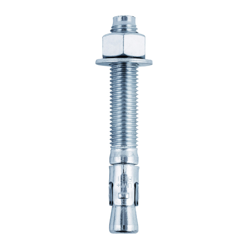
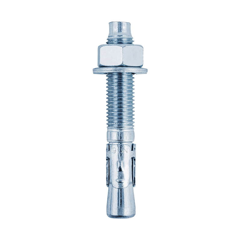
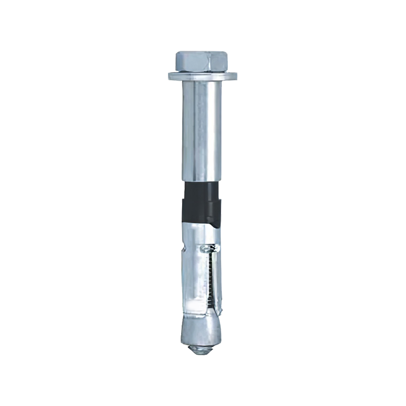
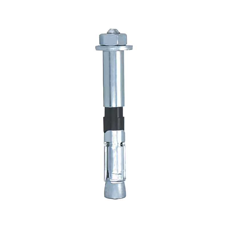
A threaded fastener may be used with a matching nut, a tapped hole, an internally threaded insert or another threaded component. Bolts, screws, studs, threaded rods and some specialized anchors are common examples.
The term threads and fasteners covers both the geometry of the thread and the mechanical component carrying that thread. Thread compatibility is essential. Two components may appear similar in diameter but still be incompatible because of different pitches, thread angles or dimensional standards.
A thread formed around the outside of a bolt, screw, stud or threaded rod.
A thread formed inside a nut, tapped hole or threaded insert.
The axial length over which matching internal and external threads contact each other.
A bolt normally passes through unthreaded holes in the assembled parts and is secured with a nut. The bolt and nut work together to generate clamping force.
A screw may enter a tapped hole or form its own mating thread in a suitable material. Screws are available with many head forms and drive styles.
A stud is commonly threaded at both ends or along its entire length. One end may remain installed in a component while a nut secures the removable part.
Threaded rod is used for supports, frames, suspended systems and assemblies requiring adjustable positioning over a longer distance.
A tool applies torque to the head, nut or drive feature of the threaded fastener.
The helical thread converts rotation into linear movement along the fastener axis.
The fastener head and nut, or the screw head and tapped component, compress the assembled parts together.
The fastener stretches elastically while the joined parts remain compressed, producing preload.
The resulting preload helps resist joint separation, relative movement and vibration-induced loosening.
A threaded fastener can create a removable, semi-permanent or adjustable mechanical assembly. The connection may be disassembled for inspection, repair or replacement without cutting or destroying the joined components.
Threaded connections can also create precision-adjustment assemblies, tensioning systems, structural joints, sealing joints and equipment mounting points.
Fasteners with threads on both ends are generally called studs or double-end studs. They do not normally have a conventional bolt head. One threaded end may be installed permanently or semi-permanently in a tapped hole, while the opposite end receives a nut.
This arrangement is useful when the base component should not experience repeated thread wear. The stud remains in place while the nut is removed during maintenance.
Threaded fasteners are reliable when properly selected and installed, but several recurring problems can reduce joint performance. These problems usually involve preload, thread condition, material compatibility or service loading.
Vibration, joint movement, embedment of rough surfaces and insufficient preload can reduce clamping force over time.
Control MethodApply the correct tightening method and use an appropriate locking strategy where required.
Internal or external threads can shear when engagement length is insufficient or the mating material is too weak.
Control MethodIncrease engagement length, select a suitable material combination and avoid excessive torque.
Excessive preload, overload, fatigue, hydrogen-related damage or stress concentration may cause the fastener to break.
Control MethodSelect an appropriate property class, control tightening and evaluate cyclic loading.
Misalignment during initial engagement can damage the first thread turns and prevent accurate tightening.
Control MethodBegin engagement by hand, maintain alignment and stop if abnormal resistance appears.
Moisture, chemicals, salt and incompatible metals can reduce the effective fastener cross-section or lock the threads.
Control MethodMatch the fastener material and coating to the operating environment.
Adhesive wear between mating threads can cause seizure, particularly in some metal combinations under high installation pressure.
Control MethodControl installation speed, surface condition, lubrication and material pairing.
| Observed Condition | Possible Cause | Technical Effect | Inspection Focus |
|---|---|---|---|
| Nut rotates without tightening | Stripped internal or external threads | Required preload cannot be developed | Thread profile, material strength and engagement length |
| Fastener loosens after operation | Low preload, vibration or joint settlement | Joint movement and fatigue risk increase | Torque method, mating surfaces and locking arrangement |
| Bolt breaks near first engaged thread | Stress concentration, overload or fatigue | Complete loss of clamping force | Fracture surface, load history and fastener grade |
| Threads are damaged during assembly | Cross-threading, contamination or wrong pitch | Inaccurate torque and reduced engagement | Thread compatibility and installation alignment |
| Fastener cannot be removed | Corrosion, galling, deformation or excessive tightening | Maintenance time and component damage increase | Surface condition, environment and lubrication practice |
| Joined parts slide under load | Insufficient clamp force or smooth contact surfaces | Shear load transfers directly into the fastener body | Preload, friction condition and joint design |
Non threaded fasteners do not rely on helical threads to produce attachment or clamping. They may use deformation, interference, spring force, a locking shape or a separate retaining feature.
The choice between threaded and non threaded fasteners depends on assembly speed, required removability, load direction, vibration, available space and production volume.
Create a permanent or semi-permanent joint by deforming the rivet body.
Align parts, transmit shear loads or form pivots without a threaded connection.
Fit into grooves to prevent axial movement of components on shafts or inside bores.
Use spring force or formed geometry for fast installation and retention.
Fit between a shaft and hub to transmit torque and prevent relative rotation.
Depend on dimensional interference between mating parts to maintain the connection.
A complete threaded fastener specification requires several measurements. Stating only the outside diameter is rarely sufficient because fasteners with the same diameter may have different pitches, lengths, head forms or mechanical properties.
The basic external diameter used to identify the thread size.
Determines thread compatibility and contributes to tensile and shear capacity.
The axial distance between adjacent thread crests.
Distinguishes coarse, fine and specialized thread series.
The number of thread turns within a defined length.
Commonly used to identify some thread systems instead of direct pitch.
The specified distance from the relevant head reference point to the end.
Must accommodate the joint thickness, washers, nut and required protrusion.
The portion of the fastener containing usable external threads.
Affects nut placement and whether unthreaded shank passes through the shear plane.
Head width, height, diameter, bearing area and drive dimensions.
Determines tool access, seating area and available installation space.
The length of contact between the external and internal threads.
Influences stripping resistance and load distribution through the mating threads.
The total thickness of the materials clamped by the fastener.
Helps determine the correct fastener length and unthreaded shank position.
Nominal thread diameter of 10 mm
Thread pitch of 1.5 mm
Nominal fastener length of 60 mm
A complete order or technical drawing may also state the head type, drive type, thread tolerance, material, mechanical property class, coating, washer arrangement and quantity.
Coarse threads have a larger pitch and fewer threads over the same axial distance. They are commonly selected for general assembly and materials where rapid installation and resistance to thread damage are important.
Fine threads have a smaller pitch and more threads within the same axial distance. They can provide finer adjustment and a larger tensile stress area for the same nominal diameter.
Suitable for a wide range of indoor machinery, frames and general mechanical connections.
Selection FocusMechanical grade, coating and operating humidity
Used where higher mechanical strength, fatigue performance or controlled heat treatment is required.
Selection FocusProperty class, hardness and service loading
Selected for humid, outdoor, hygienic or corrosive environments requiring improved corrosion resistance.
Selection FocusEnvironmental exposure and galling control
Used in electrical, decorative or specialized applications requiring conductivity or corrosion performance.
Selection FocusMaterial strength and mating-component compatibility
Identify the number of parts, total grip length, hole condition, required removability and available tool access.
Determine whether the fastener will experience tension, shear, bending, vibration, fatigue or combined loading.
Choose the nominal diameter, pitch, thread form and engagement length according to the mating component and load requirement.
Match the fastener strength and corrosion resistance to the connected materials and operating environment.
Establish the installation torque, lubrication condition, tightening sequence and inspection method.
Ensure the fastener can be installed, inspected and removed using the available space and maintenance tools.
Clear application information helps determine the appropriate threaded fastener dimensions, material, mechanical grade, head form, drive type and surface treatment. A complete specification also reduces the risk of incompatible threads or insufficient engagement during assembly.
They are bolts, screws, studs, rods and related components that use internal or external threads to create a mechanical connection.
A headless threaded fastener is commonly called a stud or threaded rod, depending on its length, thread coverage and intended application.
They are more commonly called double-end studs. A bolt normally has a formed head on one end.
Threaded joints are normally removable, but corrosion, locking compounds, deformation or restricted access can make practical removal difficult.
Common causes include insufficient preload, vibration, surface settlement, temperature change and relative movement between joined parts.
The essential measurements include nominal diameter, pitch, length, threaded length, grip length, head dimensions and required thread engagement.
Rivets, pins, clips, retaining rings and keys are common non threaded fasteners that rely on deformation, interference or mechanical retention.
No. Mating components must have compatible diameter, pitch, thread form and dimensional tolerance. Forcing mismatched threads can permanently damage both parts.


Contact Us