
 English
 中文简体
中文简体 русский
 Español
How Deep Should a Wedge Anchor Go Into Concrete? Minimum Embedment Explained
2026-09-21A 1/2 in. wedge anchor with only 2 in. of thread sitting inside a 4 in. slab will pass a hand test and still fail its first torque check. Pull-out resistance, shear value, vibration tolerance and long-term creep behaviour all trace back to one number: how far the expansion clip sits below the concrete surface.
The short answer: a wedge anchor must reach a minimum embedment depth of roughly 4.5 to 7 times its nominal diameter, as published by the anchor manufacturer. For the most common sizes that works out to 1-1/8 in. to 1-3/4 in. for a 1/4 in. anchor, 1-11/16 in. to 2-5/8 in. for 3/8 in., 2-1/4 in. to 3-1/2 in. for 1/2 in., and 4-1/2 in. to 7 in. for a 1 in. anchor. The drilled hole must then be at least 1/2 in. deeper than the embedment, so the anchor never bottoms out before it is fully seated.
That is the technical answer. The practical answer is messier, because embedment depth interacts with slab thickness, edge distance, hole cleaning, concrete compressive strength and the torque you actually apply at the end. Each of those is handled below, with the numbers a site engineer or purchasing team needs before committing to an order.
Quick Reference: Minimum Embedment by Anchor Diameter
Two benchmarks dominate the market. The 4.5 × diameter figure is the leaner published minimum found in many technical catalogues for standard-weight concrete. The 7 × diameter figure is the conservative benchmark that pushes the failure mode away from concrete cone pull-out and toward steel yielding, which is what most structural specifications prefer. Where a project has a stamped drawing, the drawing wins. Where it does not, the manufacturer's printed table wins.
| Nominal Diameter | Minimum Embedment (4.5 × d) | Conservative Embedment (7 × d) | Suggested Hole Depth (minimum + 1/2 in.) |
|---|---|---|---|
| 1/4 in. | 1-1/8 in. | 1-3/4 in. | 1-5/8 in. |
| 3/8 in. | 1-11/16 in. | 2-5/8 in. | 2-3/16 in. |
| 1/2 in. | 2-1/4 in. | 3-1/2 in. | 2-3/4 in. |
| 5/8 in. | 2-13/16 in. | 4-3/8 in. | 3-5/16 in. |
| 3/4 in. | 3-3/8 in. | 5-1/4 in. | 3-7/8 in. |
| 1 in. | 4-1/2 in. | 7 in. | 5 in. |
Suggested drilled hole depth by anchor diameter
A useful sanity check sits alongside the table: the hole is always deeper than the embedment, and the embedment is always counted only from the concrete surface down to the top of the expansion clip — never from the top of the anchor, and never including the fixture plate, washer or nut.
Why Embedment Depth Controls Almost Everything
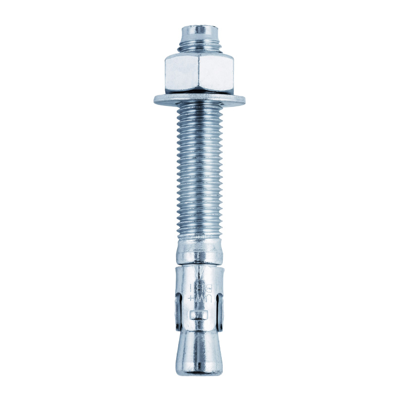
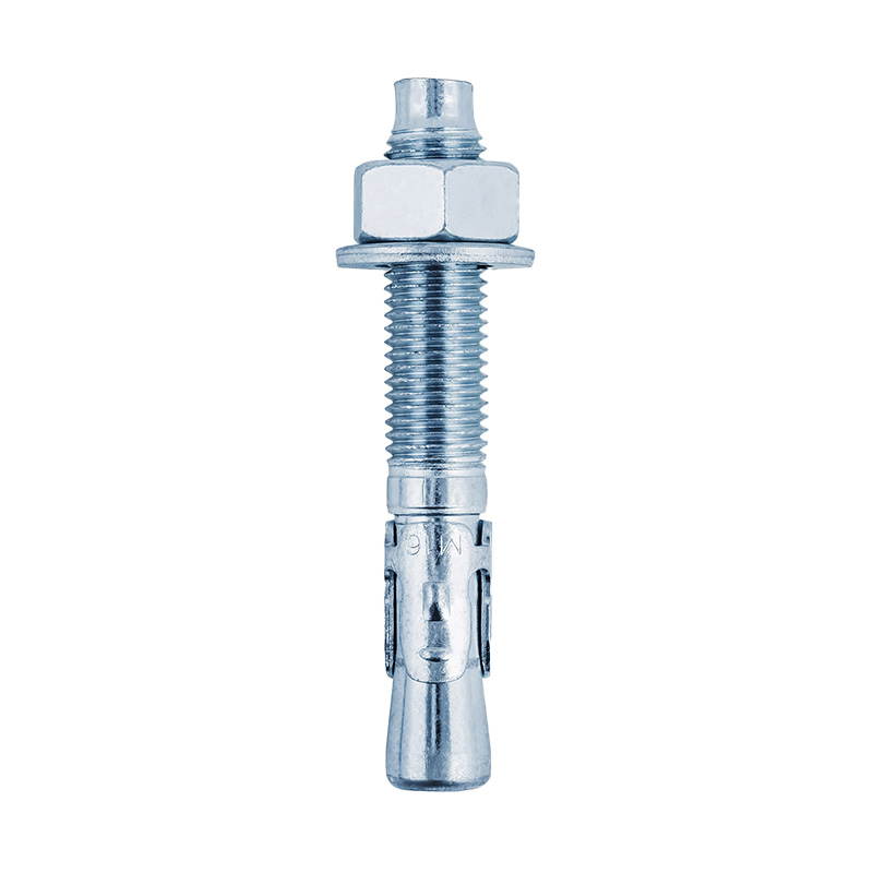
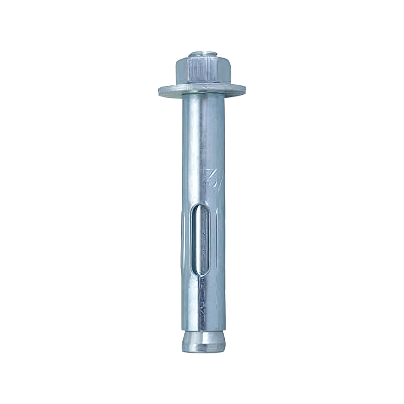
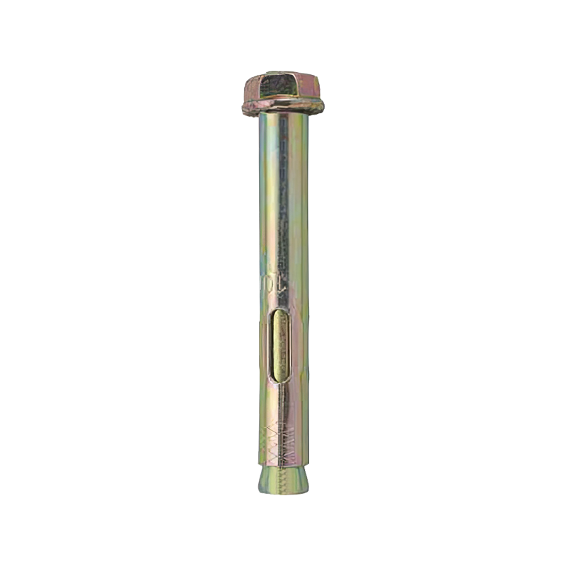
A wedge anchor holds by transferring load into the concrete through a truncated cone. When the nut is tightened, the wedge at the bottom of the stud is drawn into the expansion clip, the clip expands and presses against the wall of the drilled hole. Load travels down the stud, into the clip, out into the concrete, and then spreads radially through that cone.
The cone gets wider as the anchor goes deeper
The volume of concrete resisting pull-out grows with embedment. A 1/2 in. anchor set at 2-1/4 in. mobilises a shallow, narrow cone. The same anchor set at 3-1/2 in. mobilises a deeper cone with substantially more surface area, so the stress on the concrete at any one point drops. That is the whole reason a deeper setting is stronger — it is not the steel that changes, it is the amount of concrete doing the work.
Failure mode is the real target
Concrete cone pull-out is a brittle failure. It gives little warning, it can propagate to adjacent anchors, and in a row of anchors it can cascade. Steel yielding is ductile. It stretches, it warns, it does not suddenly remove the connection. Increasing embedment is one of the few levers that shifts the balance from the first failure mode toward the second, which is why specifications that care about seismic or fatigue behaviour rarely accept the absolute minimum published value.
How to Calculate the Hole Depth for Your Own Job
The calculation is short, but it is done in the wrong order surprisingly often. Depth first, anchor length second — not the other way round.
- Establish the embedment requirement. Read the manufacturer's table for the specific diameter and the specific base material. Add the project specification if it is stricter.
- Add 1/2 in. of clearance. This is the buffer that prevents the anchor from bottoming out on drilling dust or on a rough hole bottom.
- Check the slab thickness. The base material must be thick enough to contain the full embedment without breaking through. As a working rule, look for a slab at least 1.5 times the embedment, and confirm against the published minimum base thickness.
- Work out the anchor length. Take the embedment, add the thickness of the fixture being fixed, add the washer, add the nut, and add three to five exposed threads for adjustment.
- Confirm the drill bit matches the anchor diameter exactly. A wedge anchor of 1/2 in. needs a 1/2 in. bit — not a worn one that has drifted to 17/32 in.
The common trap is ordering the anchor by overall length alone. A 1/2 in. × 4 in. wedge anchor is not automatically usable in a 4 in. slab. If the fixture is 1 in. thick and the embedment is 2-1/4 in., the arithmetic gives 3-1/4 in. plus washer and nut, which is already tight. Multiply the same numbers with a 3-1/2 in. embedment and the 4 in. anchor is clearly too short.
Too Shallow, Correct, and Oversized: What Each One Costs You
Drilling errors fall into three buckets, and they do not carry the same risk. Being too shallow is a real defect. Being deeper than necessary is usually harmless. Being just barely at the minimum, with no margin for site variation, is where most quality disputes start.
| Hole Condition | What Happens | Risk Level | Corrective Action |
|---|---|---|---|
| Hole shallower than the required embedment | The anchor bottoms out before the clip is fully below the surface. The clip may sit partly in the dust zone. Torque either will not hold or the anchor spins. | High | Re-drill deeper, or relocate the hole. Do not shorten the anchor. |
| Hole exactly at minimum embedment with no clearance | The anchor seats correctly on a clean day, but dust accumulation or a rough hole bottom can reduce effective embedment. | Moderate | Add the 1/2 in. clearance. It costs nothing. |
| Hole deeper than the anchor length | Normal and acceptable, provided the anchor still reaches full embedment and the hole does not break through the far side. | Low | None. Deeper holes are permitted. |
| Hole drilled through the slab | The anchor can be driven below the far surface. Tightening may push the clip out of the concrete entirely. | High | Abandon the hole. Relocate or use a shorter anchor in a thicker section. |
| Hole drilled at an angle | Effective embedment is reduced by the cosine of the angle, and the clip loads the hole wall unevenly. | Moderate to high | Re-drill perpendicular. Use a drill guide on deep holes. |
There is a persistent belief on site that if the hole is deeper than the anchor, the anchor will somehow slide down and lose grip. It will not. The expansion clip locks against the hole wall as soon as torque is applied. The only genuine concern with an over-deep hole is the through-drill case, where the far side of the slab is open.
Base Material Thickness: The Constraint That Kills More Projects
Most depth problems are not drilling problems at all — they are slab thickness problems. A 5/8 in. wedge anchor at a conservative 4-3/8 in. embedment simply does not exist inside a 4 in. slab. No amount of technique fixes that; the specification has to change.
Work backwards from the slab
Take the available slab thickness, subtract the required minimum base material thickness, and see what is left. If a 4 in. slab has a published minimum base thickness of 4-3/4 in. for a given anchor, that anchor is not eligible — regardless of what the embedment table says. Options in that situation include reducing the anchor diameter, switching to a shallower-embedment anchor type, adding a through-bolt detail, or using a cast-in solution.
Watch for the thin topping layer
Composite decks, elevated slabs with a topping slab, and repaired floors often present a thin, higher-strength wearing layer over a weaker structural layer. The clip sits in the structural layer, not the topping. If the topping is 1 in. thick and the effective embedment starts below it, the numbers in the catalogue no longer apply directly. Coring a test hole and measuring layer by layer is worth the fifteen minutes.
Edge Distance and Spacing: Embedment Only Works If the Cone Fits
A deep embedment in the middle of a slab is worth nothing if the anchor sits 3 in. from a free edge. The cone has to develop inside the concrete. If it intersects an edge, the failure surface is truncated and pull-out capacity drops — sometimes by more than half.
Typical published minimums sit around 1.5 times the embedment for edge distance and roughly 2 to 3 times the embedment for centre-to-centre spacing, though values vary widely between anchor families and between cracked and uncracked concrete assumptions. The deeper the embedment, the larger these minimums become — this is why specifying a deeper anchor to gain capacity can backfire on a narrow pier or a short sill plate.
For a closer look at how these two parameters interact with the load path, the discussion on how spacing and edge distance affect ultra wedge anchor performance covers the reduction factors in more detail.
Cracked concrete
Assume cracked sections near tension zones, anchors in seismic categories, and anchors near control joints. Reduction factors apply, and deeper embedment is usually the cheapest way to recover capacity.
Uncracked concrete
More forgiving. Standard published values usually apply, but site verification still matters because a hairline crack at the hole location is easy to miss.
Lightweight concrete
Lower unit weight, lower breakout resistance. Many manufacturers require edge and spacing values to be divided by 0.75 and may restrict the anchor type altogether.
Concrete Strength, Bit Condition and Hole Cleaning
Three variables quietly erode the embedment you thought you had.
Compressive strength of the base
Published anchor tables are normally written for a defined compressive strength, commonly in the range of 3,000 to 4,000 psi for standard-weight concrete. Below that, published capacities no longer apply. There is no reliable field adjustment for a 2,000 psi slab other than reducing the load or changing the anchor; adding embedded depth helps but does not restore a table value.
Bit condition and hole diameter
A worn carbide bit drills oversized. An oversized hole means the clip has farther to expand before it contacts the wall, and the resulting contact pressure is lower. A rotary hammer in hammer-only mode without rotation, or a bit used well past its service life, produces a hole that is out of tolerance in both straightness and diameter. Measure a sample hole with a caliper or a plug gauge during the first day of installation and keep measuring.
Dust removal
Dust at the bottom of a hole shortens effective embedment by exactly the depth of the dust column. In a 2-3/4 in. hole with half an inch of fines, a 1/2 in. anchor loses close to 20 percent of its intended embedment. Blow out the hole with filtered compressed air, brush with a nylon hole brush, and blow again — twice through the full cycle. On overhead or horizontal work, add a vacuum attachment.
Field check worth adopting: before setting any anchor, drop the stud into the empty hole and mark the surface level on the stud with a paint pen. Pull it out and measure the marked thread length. If the marked length is less than the required embedment, the hole is not deep enough. This takes ten seconds and catches the problem before it becomes permanent.
Torque Values: The Step That Actually Verifies the Embedment
Torque is not just a tightening routine. It is the only field test that tells you whether the clip is properly engaged in sound concrete. An anchor set at the correct depth in a clean hole will hold torque. An anchor that is shallow, in dust, or in a cracked zone will not, and the nut will either spin down or the whole anchor will turn in the hole.
| Nominal Diameter | Typical Installation Torque | Signs the Setting Has Failed |
|---|---|---|
| 1/4 in. | 6–8 ft-lb | Nut spins without resistance; anchor lifts on tightening |
| 3/8 in. | 25–30 ft-lb | Torque falls away below 25 ft-lb; anchor rotates |
| 1/2 in. | 40–45 ft-lb | Anchor turns in the hole; base material cracks around the hole |
| 5/8 in. | 60–75 ft-lb | Water or dust bleeds from the hole during tightening |
| 3/4 in. | 110–150 ft-lb | Anchor draws upward noticeably; torque will not stabilise |
| 1 in. | 200–250 ft-lb | Marked embedment line rises above the concrete surface |
Use a calibrated torque wrench rather than an impact gun. Impact tools apply torque in short spikes, which can over-torque the stud, crack the surrounding concrete, or strip the thread before the operator notices. Where an impact gun is unavoidable, run it at reduced setting and finish by hand.
Common Mistakes That Undo a Correct Embedment
- Drilling the hole to the anchor length instead of the embedment plus 1/2 in. clearance.
- Setting the anchor with the nut already threaded on, which prevents the stud from being driven to full depth.
- Hammering the anchor home with force instead of light taps until the washer contacts the fixture.
- Reusing a hole after a failed setting. Once the hole wall has been damaged by a spinning clip, the hole cannot be recovered; relocate it.
- Over-tightening to "make sure". Excessive torque cracks the concrete and reduces capacity rather than increasing it.
- Filling the annular gap with adhesive. Wedge anchors are mechanical devices and are not designed for adhesive-assisted installation.
- Leaving the anchor loose overnight and tightening after other trades disturb the fixture.
- Assuming every anchor in a batch behaves the same. Measure the setting depth on the first anchor of each row and after any bit change.
Choosing the Anchor That Matches the Depth Requirement
Depth requirements vary by project, so the anchor range has to cover the spread rather than a single size. For projects where the specification calls for the conservative 7 × diameter embedment, a longer stud of the same diameter is usually enough — the clip position is what changes, not the working mechanism. For projects working to a tight slab thickness, a shorter-embedment designed anchor or a different diameter may be the only route that fits.
Applications differ too. A 1/2 in. anchor in a curtain wall base plate on a 6 in. slab has very different constraints from a 3/4 in. anchor fixing a crane rail in a 12 in. foundation block. In general terms, construction and industrial applications for metric wedge anchors tend toward deeper embedments, because the loads and the vibration environment both demand more concrete doing the work.
Shallow embedment situations
Thin slabs, retrofit work, overhead soffits, and locations where the far side cannot be accessed. Depth is capped by geometry, so anchor selection has to start from the slab rather than the load.
Deep embedment situations
Heavy machinery bases, structural steel columns, bridge bearings, tunnel segments and rail infrastructure. The embedment is driven by the specification, and the anchor length follows from the fixture stack-up.
Corrosive environments
Coastal, marine and chemical plants. Embedment depth is unchanged, but coating thickness on the stud has to be accounted for when confirming exposed thread and hole clearance.
Frequently Asked Questions
How deep should a 3/8 in. wedge anchor go into concrete?
Most catalogues publish a minimum embedment around 1-11/16 in. for a 3/8 in. anchor in normal-weight concrete, with conservative specifications calling for roughly 2-5/8 in. The drilled hole should be at least 1/2 in. deeper than whichever figure applies, so 2-3/16 in. to 3-1/8 in. of hole depth is typical.
Is it a problem if I drill deeper than the anchor is long?
No, provided the hole does not break through the far side of the slab. The anchor seats on the expansion clip, not on the hole bottom. The only genuine risk with an over-deep hole is a through-drill, where the anchor can be driven below the concrete surface and lose contact entirely.
Can I use a 1/2 in. wedge anchor in a 4 in. slab?
Only at the leaner end of the embedment range. A 2-1/4 in. embedment plus the required base thickness usually fits within a 4 in. slab; a 3-1/2 in. conservative embedment generally does not. Check the published minimum base material thickness for the exact anchor before committing.
What happens if the hole is too shallow?
The stud bottoms out before the expansion clip clears the dust zone. Torque will not hold, the anchor may spin in the hole, and pull-out capacity can drop by a large margin. The hole must be re-drilled deeper or abandoned and relocated. Shortening the anchor is not an acceptable fix.
Does concrete strength change the depth I need?
Yes. Published anchor tables assume a defined compressive strength, commonly between 3,000 and 4,000 psi for standard-weight concrete. Below that, the published capacity no longer applies. Increasing embedment improves things, but it does not restore the table value in a genuinely weak slab.
How many threads should remain exposed after tightening?
Three to five full threads above the nut is a practical target. Fewer than three means the anchor length was marginal for the fixture stack-up. Significantly more means the anchor is longer than needed and the extra thread is simply unused.
Should I clean the hole before setting the anchor?
Always. Dust at the bottom of the hole reduces effective embedment by its own depth. Blow, brush, blow again, and repeat. In a 2-3/4 in. hole, half an inch of fines can cut effective embedment by close to twenty percent.
What torque should I apply to a 1/2 in. wedge anchor?
Around 40 to 45 ft-lb is typical, but the exact figure depends on the manufacturer, the coating and the grade. Follow the tag on the box. Use a calibrated torque wrench, not an impact gun, and stop if the anchor begins to turn or the concrete cracks.
What to Put in a Purchase Enquiry
Most depth-related disputes trace back to an incomplete enquiry. Telling a supplier only "1/2 in. wedge anchors, 5,000 pieces" leaves the anchor length, embedment assumption and coating open, and the answer that comes back may not match the site condition.
Send the anchor diameter, the required embedment depth or the base slab thickness, the fixture thickness, the base material and its assumed compressive strength, the edge distance and spacing available, the environmental exposure, and any torque figure already written into the drawing. With those inputs, the anchor length follows arithmetically and the depth question answers itself.
Anchor studs in the standard diameter range are produced on automatic cold-forming equipment with in-house dimensional inspection, and the depth-critical dimension — the distance from the clip seat to the top of the conical wedge — is controlled through the production run rather than checked at the end. That is the dimension that decides whether a published embedment value is actually achieved in the field.


Contact Us